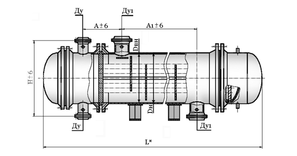
Shell-and-tube heat exchangers with a floating head
Designed for heating and cooling liquid and gaseous media in the technological processes of the oil, chemical and gas industries.
Heat exchangers shell and tube multi-pass through the pipe space, vertical and horizontal in execution. Material design depending on the applied average and operating parameters.
Design, applied materials, basic design characteristics and parameters meet international standards.

Technical characteristics of heat exchangers
| Diameter of casing, mm | Pressure Ру, МPа | dn pipes | Number of strokes | Heat transfer surface, m2 | L, mm | H, mm | Dy, mm | Dy1, mm | А, mm | А1, mm | Weight (not more than), kg | |||
|---|---|---|---|---|---|---|---|---|---|---|---|---|---|---|
| Дн | Дв | 3000 | 6000 | 9000 | ||||||||||
| 325 | - | 1,6;2,5;4,0 | 20 | 2 | 13 | 26 | - | 3960- 6705 |
600 | 100 | 100 | 450 | 2350- 5350 |
1550 |
| 25 | 10 | 20 | - | 1480 | ||||||||||
| 426 | 400 | 1,6;2,5;4,0;6,3 | 20 | 2 | 23 | 46 | - | 3690- 6750 |
714- 810 |
100 | 100 | 500- 550 |
2500- 5250 |
2750 |
| 25 | 19 | 38 | - | 2650 | ||||||||||
| 530 | 500 | 1,6;2,5;4,0;6,3;8,0 | 20 | 2 | 38 | 76 | - | 3835- 7400 |
954- 1130 |
150 | 150 | 550- 800 |
2200- 5200 |
4430 |
| 25 | 31 | 62 | - | 4270 | ||||||||||
| 630 | 600 | 1,6;2,5;4,0;6,3;8,0 | 20 | 2 4 |
- | 96 86 |
144 129 |
6900- 10800 |
1060 - 1300 |
200 150 |
200 | 600- 1000 |
5100- 8100 |
6720 6700 |
| 25 | 2 4 |
- | 96 86 |
144 129 |
200 150 |
200 | 6500 6480 |
|||||||
| - | 800 | 1,6;2,5;4,0;6,3;8,0 | 20 | 2 4 |
- - |
212 197 |
318 295 |
7465 - 11000 |
1060 - 1300 |
250 200 |
250 | 700- 1250 |
5100 - 7200 |
14250 |
| 14150 | ||||||||||||||
| 25 | 2 4 |
- - |
170 157 |
255 235 |
250 200 |
250 | 13850 | |||||||
| 13710 | ||||||||||||||
| - | 1000 | 1,6;2,5;4,0;6,3 | 20 | 2 4 |
- - |
346 330 |
519 495 |
7615 - 11250 |
1558 - 1860 |
300 200 |
300 | 750- 1330 |
5000 - 7200 |
2300 |
| 22850 | ||||||||||||||
| 25 | 2 4 |
- - |
284 267 |
426 400 |
300 200 |
300 | 23050 | |||||||
| 22800 | ||||||||||||||
| - | 1200 | 1,6;2,5;4,0;6,3 | 20 | 2 4 |
- - |
514 494 |
771 741 |
7655 - 11400 |
1780 - 1900 |
300 250 |
300 | 820- 1400 |
4760 - 7760 |
3550 35400 |
| 25 | 2 4 |
- - |
423 403 |
635 604 |
300 250 |
350 | 33500 33400 |
|||||||
| - | 1400 | 1,6;2,5;4,0 | 20 | 2 4 |
- - |
715 693 |
1072 1040 |
7915 - 11100 |
1980 - 2000 |
350 250 |
350 | 1020- 1270 |
4660 - 7760 |
34460 34450 |
| 25 | 2 4 |
- - |
584 561 |
876 841 |
350 250 |
350 | 35550 35500 |
|||||||
The shell-and-tube heat exchanger is used today to change the temperature of the working medium, which is in liquid or vapor form, while ensuring the complete safety of its aggregate state. The use of such equipment is carried out in various technological processes in the chemical, petrochemical, oil refining and gas industries.
Heat exchangers are often used when there are significant relative movements of pipes and casing, since in such equipment one of the grids is not connected to the casing and can be completely moved along the axis in the event of thermal elongations.
The shell-and-tube heat exchanger can withstand the pressure from the side of the refrigerant not more than 1 MPa, and in the intertubular space the pressure can reach already 2.5 MPa, which is their main feature in comparison with the standard options differing in the lower maximum permissible pressure.
Also, the originality of the design of this type of shell-and-tube heat exchanger is also in the fact that the pipe flaps inside the casing are fixedly fixed exclusively from one end of the device while the tube bundle is completely free from the opposite side. Due to such an original design, the risks of deformation of pipe assemblies are completely eliminated in the event of a sudden temperature drop of that medium, due to which heat exchange is ensured.


